
Wood-Concrete / Technical Specification

Wood-Concrete Al-Fer Dry Connector
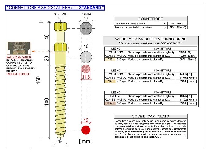
Standard Wood-Concrete
Data Sheet
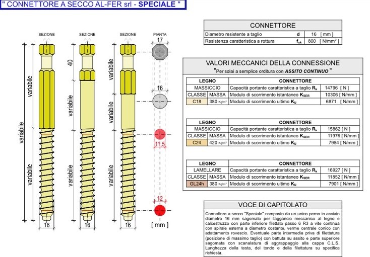
Special Wood-Concrete
Data Sheet
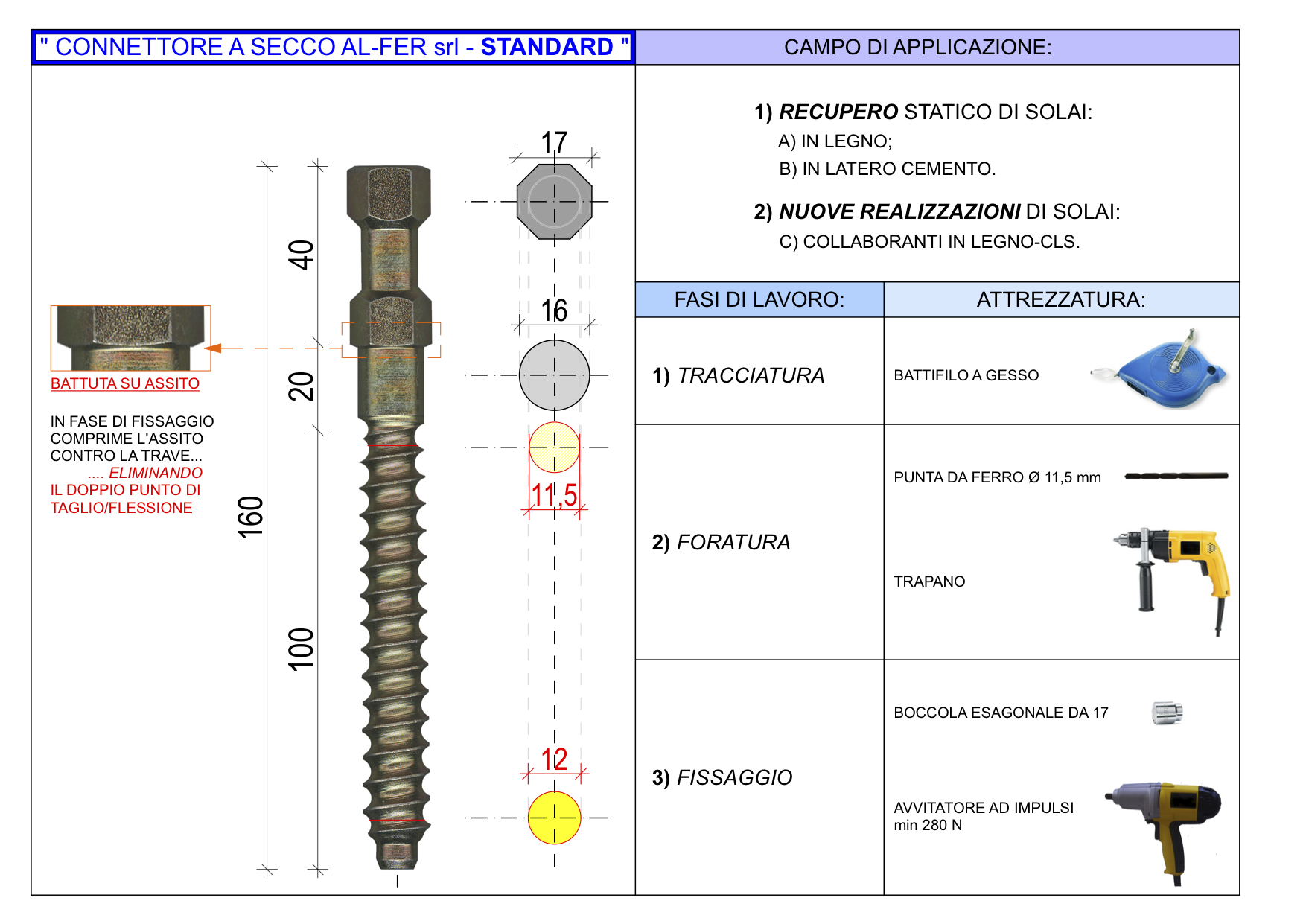
Standard Wood-Concrete
Product Sheet


Standard Wood-Concrete
Data Sheet
Special Wood-Concrete
Data Sheet
Standard Wood-Concrete
Product Sheet
Technical Description
Connector composition
The Al-Fer dry connector consists of a single steel body obtained from a Ø 16 bar suitably machined with wood thread to be secured on the beam.
The bar is smooth in the portion that corresponds to the floor board, done in order to obtain the maximum diameter of the connector (ø16). It is unscrewed with hexagonal head and characteristic grooves specifically designed to connect to the concrete of the slab.
The lower part, threaded with a continuous screw, is made using a equal diameter of the outer spiral while the central section is conical with a reverse fit. This is done so that the fixed tip is more resistant to hooking near the neutral axis of the wooden beam.
It can be divided into three parts:
While head and thread are always present, the central body can sometimes be omitted. The following pages describe element details and specify their function.
The Head

For mixed Timber-Concrete and Concrete-Concrete structures, its main elements, the grooves and stop perfom a dual function. The first allows the mechanical coupling of the concrete that can be diagrammed through a cone-resistant mechanism with a downwards angle of 45°. Thanks to unique thread, second part compresses the connector on the fixing means, creating a pre-compression effect.
The shape of the head does not allow the slab to be lifted off the interface, a phenomenon called uplift.
The Central Body

The central body has a circular cross-section with a constant diameter of 16 mm. It has the role of absorbing the greater shear and momentum forces induced by external stresses on the mixed system.
The greatest shear and momentum forces are between the central body, the head and the thread, hence the need to have an intermediate element with high geometric rigidity.
The Thread

The thread is created with the external spiral with a constant diameter of 16 mm, while the central worm is conical with reverse fit. In other words, the central core of the thread has a circular section with a diameter of 11.5 mm near the central body of the connector and gradually widens to a diameter of 12 mm at the tip. This way the fixed tip is more resistant to mechanical coupling in both wood and concrete.
This particular “taper” of the thread together with the appropriate calibration of the pre-drilled hole give the connector a considerable resistance to extraction, this means 2500 kg would be needed to extract a standard connector in a third category wood (C18) fixed perpendicular to the fibre. In wood, a pre-drill with a tip diameter of 11.5 mm is made to get a compression of the wood fibres along the circumference of the maximum section of the thread, at the 12 mm tip. Similar to a “pressure cap”, the unique thread gives the connector a mechanism for diffusing cone forces, as shown in the images above.
During the screwing phase, the wood is compressed first along the external spiral of the thread and then also along the internal part of the thread thanks to the greater section of the stem compared to the pre-drilled hole. After the connector is inserted, the stop and thread therefore generate a constraint, like a “vertical pre-compression” between the floor board and the wooden beam. Once the maturation of the concrete is obtained and the connector is put into operation, this vertical force will act as friction that will further reduce and resist the horizontal flows.